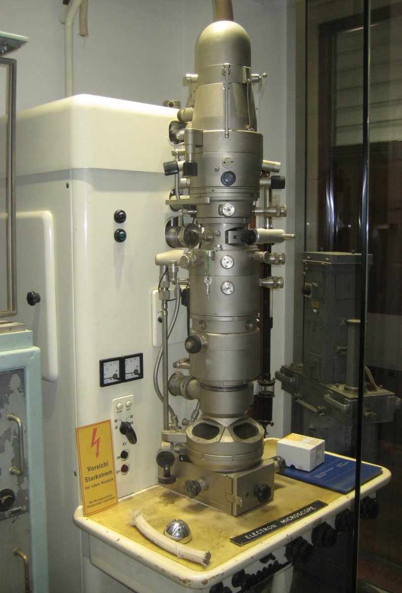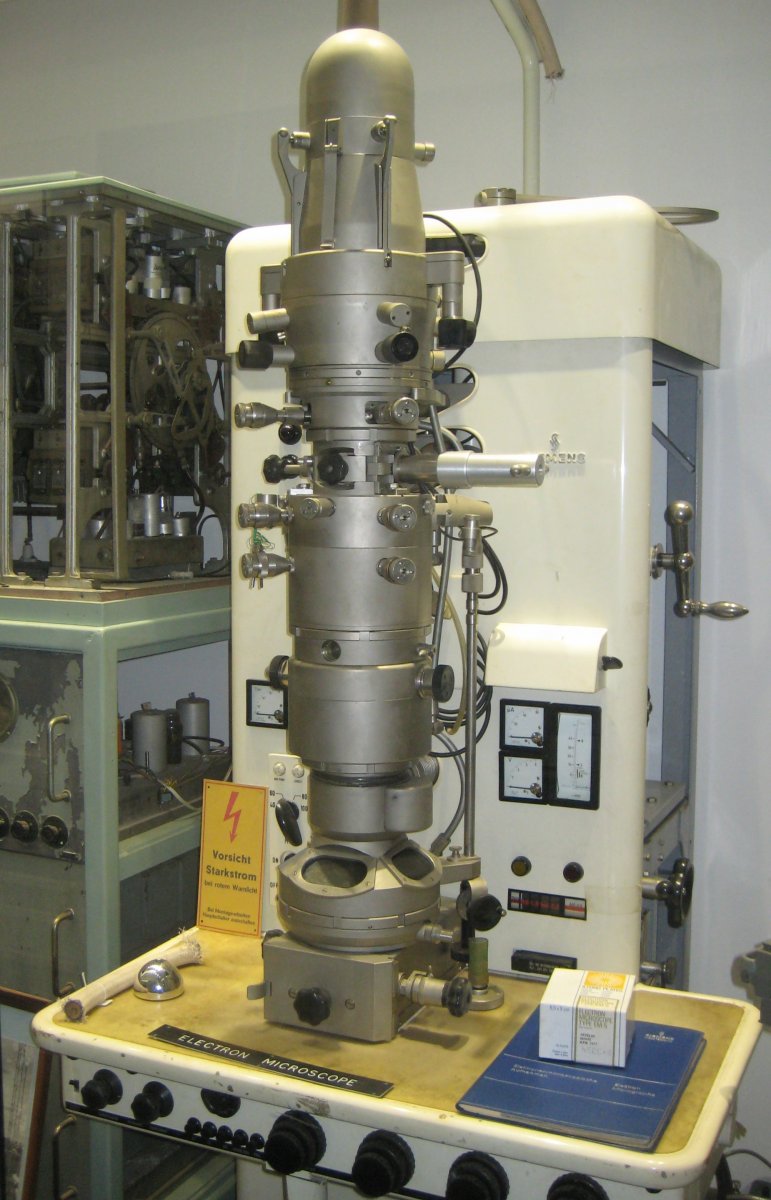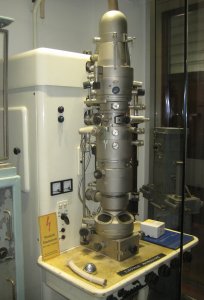
The Elmiskop 1A transmission electron microscope was made by Siemens in the early 1960’s. Purchased and used by the electron microscope centre at the University of Queensland, it was acquired by the museum in the mid 1980’s.
The electron optics column
The column consists of several sections which link together to form the complete column. These are as follows, from top to bottom in the column:
Electron source, Condensers 1 & 2, Specimen air-lock, Objective lens & Intermediate lens, Projector lens, Viewing portion, Photograph chamber
A high voltage power source, (40 – 100 kV) connects to the top of the electron source. This heats a hair pin tungsten filament which produces electrons that are propelled down the column. From here two magnetic lenses (Condensers) focus and magnify the electrons onto the specimen. Magnetic lenses perform a similar role to conventional glass lenses, but focus electrons with the use of magnetic fields.
The specimen air lock section is the area where specimens to be viewed are inserted into the column. The purpose of the air-lock in this segment is to allow specimens to be changed without completely evacuating the vacuum present in the microscope column. The image is then further refocused by the Objective and Intermediate lenses, before the projector lens projects the image onto a zinc sulfide screen for viewing. This zinc sulfide screen is mounted in the viewing portion of the column and can be viewed through the viewing portions lead glass window. If the produced image needs to be permanently recorded, the zinc sulfide screen can be slid back to reveal a photographic plate below. This photographic chamber is designed to allow not only single photographic plates to be installed but also contains a mechanism (known as a film cassette) that allows the user to rotate through and use several different photographic plates. This bottom photographic chamber also contains an airlock system similar to the specimen section which allows for photographic plates to be changed easily.
Along the length of the electron microscope column several fine adjustment nozzles are present to allow adjustment of the magnetic lenses. Four adjustments are present for each lens to allow precise regulation of magnetic field in ±x and ±y directions. More adjustment nozzles are present to allow for straight alignment of the entire length of column. The optimal resolution that this electron microscope can reach is approximately 160,000 times amplification of the specimen. JF
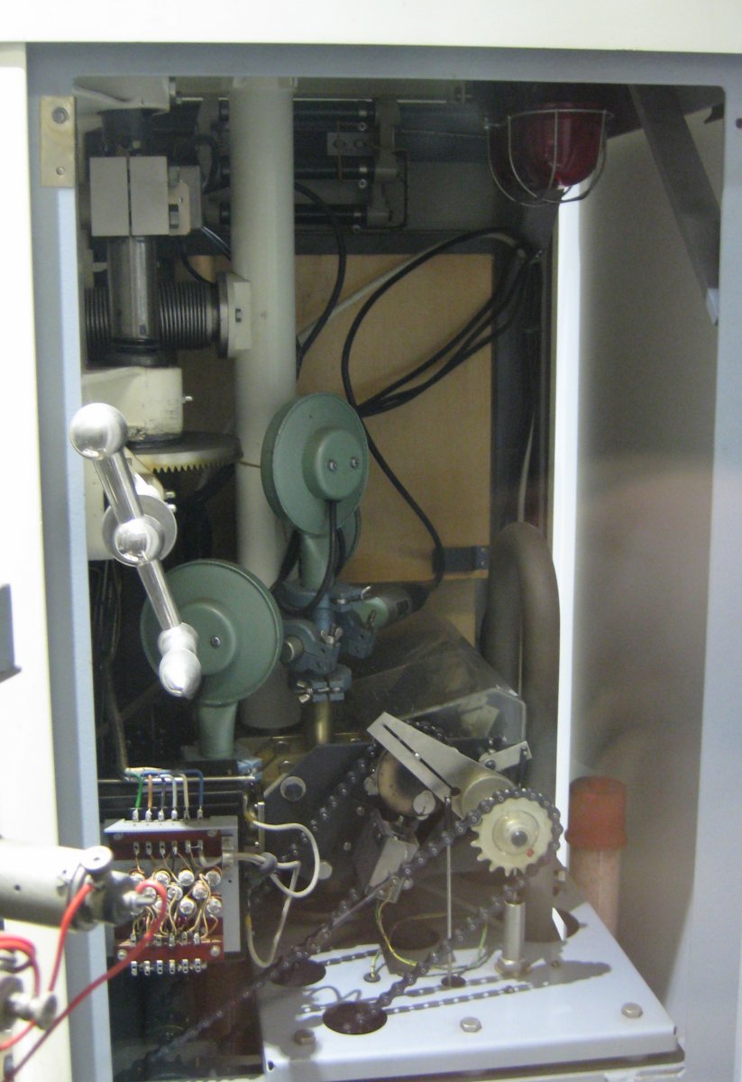
The Vacuum System
The transmission electron microscope requires a high internal vacuum (~10-4 Torr with 1 Torr = 1 mmHg = 133 Pa) to minimise attenuation of the electron beam. This is produced by a molecular pumping system consisting of a water cooled 3-stage oil diffusion pump connected in series to a water cooled 3-stage mercury vapour pump. The assembly is connected to the microscope through the oil diffusion pump via a water cooled baffle and valve block as shown in Figure 1. The valve block consists of several single chambers fitted with disc valves, which are operated by two cam systems that are turned via chains by means of a wheel and lever switch drive respectively.
In order to minimize changeover times when specimens and photographic cartridges are replaced both compartments are fitted with airlocks. This allows them to be isolated from the microscope body and greatly reduces vacuum recovery times (approx. 1 min).
Because this pumping system only begins to function at vacuums of < 1 Torr a single stage rotary pump is employed to produce the initial vacuum. This is in turn connected via a vacuum reservoir to the mercury vapour pump. The reservoir allows exposure of the photographic plates without the undesirable vibrations induced by the backing (rotary) pump and is sufficient to maintain the operating vacuum for several changes of specimen.
This design is slightly unusual in that the two diffusion pumps are coupled in series with the backing pump enabling a continuous pressure reduction from atmospheric pressure to the operating vacuum. Because the backing pump performance declines significantly at pressures < 1Torr but the primary oil diffusion pump operates most effectively at vacuums of between 10-2 and 10-4 Torr the mercury vapour pump is required to bridge this gap.
Vacuum measurements are made using two types of gauge: the Penning and Thermistor gauges. During the initial pressure reduction (> 1E-02 Torr) a thermistor gauge is used. This utilizes a semiconductor and Wheatstone bridge to measure temperature variations of a heated wire due to pressure changes. In the high vacuum regime a Penning gauge is used which utilizes a self-sustained gas discharge. The discharge current is a measure of the gas pressure.
The museum has the Operating Manual including vacuum, measurement and water cooling system schematics for a Siemens Elmiskop 1 microscope (circa. 1960) but both models have similar vacuum systems.